


Buy anything from 5,000+ international stores. One checkout price. No surprise fees. Join 2M+ shoppers on Desertcart.
Desertcart purchases this item on your behalf and handles shipping, customs, and support to Argentina.
🔵 Elevate your DIY game with crystal-clear OLED brilliance!
This 0.96" blue OLED display module features a sharp 128x64 pixel resolution driven by the SSD1306 IC, communicating via a simple 2-wire I2C interface. Designed for easy integration, it supports flexible I2C addressing and includes mounting holes for quick installation. Compatible with Arduino, Raspberry Pi, and other popular microcontrollers, it’s the perfect compact display solution for professional-grade DIY electronics and IoT projects.


| Best Sellers Rank | #2,122 in Single Board Computers (Computers & Accessories) |
| Customer Reviews | 4.4 out of 5 stars 518 Reviews |
C**Y
Great display
Works well with a little reading. I found that you DID NOT have to adjust the header file and only need to initialize the display with display.begin(SSD1306_SWITCHCAPVCC, 0x3C); Worked on both an Uno and a Mega. Uno Pinout SDA - A4 SDL - A5 GND - GND VCC - 5v Mega Pinout SDA - 20 SDL - 21 GND - GND VCC - 5v The example code for the SSD1306 really starts to push the memory of the Uno, but the Mega has no issue loading the program. Because it is an OLED, it will look dead until it has been initialized, which can be a bit confusing when you are first testing the screen. I thought I had a dud until I got it correctly initialized. Had no issues with 3.3v or 5v. Tested with a 30k Thermistor. #include <SPI.h> #include <Wire.h> #include <Adafruit_GFX.h> #include <Adafruit_SSD1306.h> #define OLED_RESET 4 Adafruit_SSD1306 display(OLED_RESET); #if (SSD1306_LCDHEIGHT != 64) #error("Height incorrect, please fix Adafruit_SSD1306.h!"); #endif #define THERMISTORPIN A0 // which analog pin to connect #define THERMISTORNOMINAL 30000 // resistance at 25 degrees C #define TEMPERATURENOMINAL 25 // temp. for nominal resistance (almost always 25 C) #define NUMSAMPLES 50 // how many samples to take and average, more takes longer #define BCOEFFICIENT 4400 // The beta coefficient of the thermistor (usually 3000-4000) #define SERIESRESISTOR 30000 // the value of the 'other' resistor int samples[NUMSAMPLES]; void setup() { Serial.begin(9600); // connect AREF to 3.3V and use that as VCC, less noisy! analogReference(EXTERNAL); // by default, we'll generate the high voltage from the 3.3v line internally! (neat!) display.begin(SSD1306_SWITCHCAPVCC, 0x3C); // initialize with the I2C addr 0x3D (for the 128x64) // init done // Show image buffer on the display hardware. // Since the buffer is intialized with an Adafruit splashscreen // internally, this will display the splashscreen. display.display(); delay(250); // Clear the buffer. display.clearDisplay(); } void loop() { uint8_t i; float average; float maxTemp; maxTemp = 0; // take N samples in a row, with a slight delay for (i=0; i< NUMSAMPLES; i++) { samples[i] = analogRead(THERMISTORPIN); delay(10); } // average all the samples out average = 0; for (i=0; i< NUMSAMPLES; i++) { average += samples[i]; } average /= NUMSAMPLES; display.clearDisplay(); display.setTextSize(1); display.setTextColor(WHITE); display.setCursor(0,0); Serial.print("Analog "); Serial.println(average); display.print("Analog "); display.println(average); // convert the value to resistance average = 1023 / average - 1; average = SERIESRESISTOR / average; Serial.print("R "); Serial.println(average); display.print("R-Val "); display.println(average); display.setTextSize(2); float steinhart; float fconvert; float convertValue; steinhart = average / THERMISTORNOMINAL; // (R/Ro)2 steinhart = log(steinhart); // ln(R/Ro) steinhart /= BCOEFFICIENT; // 1/B * ln(R/Ro) steinhart += 1.0 / (TEMPERATURENOMINAL + 273.15); // + (1/To) steinhart = 1.0 / steinhart; // Invert steinhart -= 273.15; // convert to C Serial.print(steinhart); Serial.println(" *C"); fconvert = steinhart * 1.8; fconvert = fconvert + 32; Serial.print("Temperature "); display.println("A0 Temp"); Serial.print(fconvert); Serial.println(" *F"); display.print(steinhart); display.println(" *C"); display.print(fconvert); display.println(" *F"); display.display(); delay(250); }
G**X
Very Nice Display, Easy to use Bright, Clear, and VERY high resolution
With its crystal clear display and easy I2C connection, this little OLED went easily into my project and looks terrific. The link provided to the library worked well. It is I2C address 0x3C, so don't get confused by the markings on the back of the board. I did, but used an I2C scanner and sure as heck, their docs were correct! Adafruit's library is what makes this great, and making bitmaps for images is very easy using the tool at: [...]f you are using it for Arduino (or Particle Photon, as I am in this project). I bought one to see how it would look for my project and it is going into 7 more that I am making; I just bought 8 more. Seller shipped fast and it arrived in a nice padded envelope, perfectly packed for the journey.
D**G
Almost works out of the box on latest version of Arduino IDE.
Most importantly, the hardware works fine and the i2c is a big GPIO saver. However, the supporting zip file has some "gotchas" and could use a bit of editing though the instructions are reasonably easy to follow. I'm relatively new to Arduino and I was able to connect this oLED display to an Arduino Uno R3 and upload the example sketch using Arduino IDE 1.8.1 almost immediately. Almost. My rating is based mostly on the supporting information and libraries which are downloaded from the link in the product description which make it not very friendly for new users. (1) The version of the library provided did not compile on the first try. I had to modify it (see below) to work on Arduino IDE 1.8.1 apparently because of an update to the avr-gcc compiler used by Arduino IDE 1.6.x and above. There is an Arduino Wiki on github with an FAQ that explains the issue further and points a finger at the libraries (which are provided by the seller.) To get around this, in the PROVIDED example sketch titled ssd1306_128x64_i2c: I changed: static unsigned char PROGMEM logo16_glcd_bmp[] = To: static unsigned const char PROGMEM logo16_glcd_bmp[] = (2) The libraries are modified versions of the Adafruit libraries for the Adafruit version of the 1306 display. If you have a mix of this product and the Adafruit version, be warned that to switch between them may mean either modifying the provided libraries to make them unique to this device, or uninstalling and switching libraries every time you switch devices. This is a real potential for heartburn in my opinion. (3) Don't use the stock Adafruit example Sketch in the Arduino IDE. Instead, go to the support file you downloaded to find the modified library and example sketch. It has the i2c address updated to their stock address (0x3C on the one I received) so there isn't a need to research the address or use an i2c scanner sketch on your Arduino to find the address. Also, the vendor didn't bother to update the description in their version of the Adafruit example sketch. (4) Wiring for their example sketch - display SDA to UNO pin A4; display SCL to UNO pin A5. The notations in the Sketch indicate it requires three wires (2 for i2c and one for reset) but the vendor's instructions explain that they handled the reset pin a differently. The vendor also left in the link in the top of the example sketch which points to the product sales page on Adafruit. My Arduino brand Uno R3 was able to power the display using the 5V and GND pins. If you are on the latest IDE, you should be able to get this running in little more time than it takes to install the provided libraries (the provided instructions assume you know how to do this) and upload the sketch. I want to be clear that I did not attempt to use any of the "stock" libraries or "stock" examples so any and all issues have absolutely nothing to do with Adafruit/Limor Fried whose work was used extensively to support this product.
M**C
Great display at an easy price!
I have ESP8266 controlling a dual relay for in-floor radiant heat as well as radiant towel warmers in the bathroom. Of course, this is connected via WiFi to our Home Automation Software but we still wanted a display to tell us time remaining on the towel warmer and if the software was calling for heat. This little display is going to be mounted in a Decora box along with the sensor and micro-controller. It was trivial to hookup and make work using NodeMCU/Lua. There's no documentation but the display as noted is 64x128 pixels. What's not documented is the top 16 lines are yellow and bottom 48 are blue. It actually looks pretty good and I'd prefer a two color display. (The colors are actually more legible to the naked eye than to the camera lens.) I'll be ordering a few more.
J**.
Great, inexpensive little display.
These are inexpensive and beautiful - I've used them in many projects. Note that the default address for arduino is 0x3C (7-bit. More Below). If left on constantly, there can be some "burn-in" manifested as the most-illuminated pixels becoming a bit dimmer, but A) they're inexpensive enough to replace occasionally B) still perfectly legible with burn-in. In response to some reviews questioning the resolution - I've ordered several and I can assure you they are all 128x64 - just make sure you Open the adafruit library and change the display definition to 128x64. The adafruit library works great with this display, but it's designed to work with their products, and the documentation is for their implementation. Make sure this line is uncommented, line 73 in Adafruit_SSD1306.h "#define SSD1306_128_64" there are three define lines for other sizes below, make sure those are commented out and you'll get a framebuffer that uses the whole display! As for the discrepancy with the address on the back, 0x78 in 8-bit is the same address in 0x3C in 7-bit. (0x78 in binary is 1111000, 0x3C is 111100 - the last bit of the address is the "read/write" bit, which most vendors feel should be omitted from the slave address specification, but some, for whatever reason, list the whole 8 bits. The arduino Wire library expects a 7-bit address. The full intricacies of i2c addressing are beyond the scope of an amazon comment, but I encourage you to dig deeper!) Note in the library "// Address for 128x64 is 0x3D (default) or 0x3C (if SA0 is grounded)" - so these boards are grounding the Select Address 0 pin on the SSD1306. You could change the address of the display, if you wanted to use two for example, by changing the position of that jumper with the address label (requires desoldering and resoldering). This would unground the SA0 pin and restore the chip to listening on it's default address. 0x7A, incidentally, is the 8 bit equivalency of the 7 bit address 0x3D.
C**T
works well
being a complete newb at this, still got it working on a brand new arduino/genuino 101 (took a little 3 hr class on how to get the galileo to run a bit ago, so had a smidgeon of experience). First thing I tried after the blink check (make sure your USB is plugged in all the way...took about an hour to figure that one out :-p) was to get the 128x64 I2C example to run. key things to get the example to run: grab the 1306 and GFX libraries from adafruit/github 1306.h - change the comment out for the 128x32 display to 128x64 (was in lines 62/63 for me) the I2C address was set for the 128x32 to 0x3C...left that as is as this is what we need for this display. got a ton of compile errors...quick google search let to this: 1306.ccp - comment out delay.h ( // #include <util/delay.h>) in line 28 - check for delay_ms and replace with plain delay (I didn't have that actually being used, all were already converted in the .ccp file, looks like the include was a carryover/update miss?) --> compiled fine after this and the example code uploaded and runs. hookup: connected SDA/SCL/GND to same named pins on board, vcc to 3.3V pin
P**R
Really nice display.
This is a very nice little display. When I hooked it up and ran a sketch that was a simple countdown timer the display was truncated vertically, but not horizontally, as if the code was looking at fewer pixels vertically. I checked the code in the Adafruit library and found it was doing exactly that. The code as two lines describing the pixels, one is commented out and one isn't. The correct line is commented. I simply commented the wrong line and uncommented the correct line, re-compiled and uploaded the code and everything was perfect. I really like the I2C interface which leaves basically all the pins available to other things. Another nice feature is that it will run from either the 3.3V or 5V pins on the Arduino. I tried it on both and it works great. I spent about thirty minutes modifying some sample code and found the display was very easy to use with the recommended libraries. As stated by another reviewer there is a one pixel horizontal line between the yellow portion and the blue portion which contains no LEDs. That is you can't have the blue area and yellow area touch, they will always be separated by one pixel. I knew that going in so no big deal and the separate colors really do make for a nice display with titles or icons in the yellow portion and the main body of info presented in blue.
C**T
Shoddy documentation knocks off 2 stars
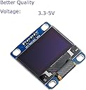
The $10 I saved versus buying the Adafruit 128x64 display is offset several times over by the 2.5 hours I spent getting the example code to compile. My trial and error process is documented at the end of the review. I'm still very new to Arduino, but have decent experience developing in C/C++. I have no qualms with needing to do some manual installation and confguration, but the directions need to be better than this. Unless I'm building a lot of an item and need the parts much cheaper, I'll likely stick to Adafruit or others with better documentation/support. I did realize before buying that the top section is only yellow and the bottom section is only blue, but the gap between those sections comes as a surprise. It's not a deal killer, but would be nice if that was noted in the description. --Using directions in IIC_OLED.zip file downloaded from the link in the description (md5sum: 538d90a29b4a8d8490e1f2c6f173be0a) --For 0.96 inch, copied Adafruit_SSD1306.h and Adafruit_GFX.h into new folders in my Arduino/libraries --Compile failed, many undefined reference errors from linker. I was wondering how this was going to work if I'm only copying headers over, but I thought maybe the libraries were already there, and only the headers were custom... --Anyway, copied over the .cpp files along with the .h files. Now I get an error stating that "variable 'logo16_glcd_bmp' must be const in order to be put into read-only section by means of '__attribute__((progmem))'" -_- --Added the 'const' keyword --That took care of the error at hand, but it still wouldn't compile... sorry, lost track of the exact error at that point. --Decided to ditch the DIYMall modified files and tried using the legit Adafruit libraries, since other amazon reviews indicated that it would work fine with those. Of course, the one thing the directions were right about is that it won't work with them. --Finally decided to install the DIYMall files in separate directories in the libraries folder, but of course that generated errors that it didn't know which Adafruit_SSD1306.h file to use. --Rather than get rid of the Adafruit libraries just to use their one-off version, I renamed the files to DIYMall_SSD1306 and DIYMall_GFX, and changed the #include lines in cpp (and one header) files to point to the correct headers, and finally it worked.
S**Y
Pin out was as described in the photo
Came as described. A lot of images of these devices show a pinout that is different to what is actually sent.
M**A
excelente producto
llego a tiempo y en excelente estado
A**I
good
best
H**A
Económico y muy funcional. Programable para Arduino y ESP32
Un poco pequeño el display. Pero cumple las expectativas de uso!
Trustpilot
1 month ago
4 days ago