⚙️ Power Up Your Projects with Precision!
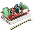
The RioRand 350W 6-60V PWM DC Brushless Electric Motor Speed Controller is a high-performance driver designed for three-phase brushless motors with Hall sensors. It features a wide voltage range, robust power output, and advanced control capabilities, making it ideal for both professional and DIY applications. With built-in safety measures and a user-friendly design, this controller is perfect for those looking to elevate their motor control experience.


| Material Type | Copper |
| Voltage | 60 Volts |
| Horsepower | 350 Watts |
| Speed | 6 Volts (DC) |
A**R
Works fine with Arduino (Sample code below)
It took a little bit to figure out the wiring. I was able to crack open my 36V hub motor and clearly read the labels but they didn't correspond to the motor controller.I did have to short the Jumper.As far as getting it to work with an Arduino:- I used an Arduino Nano to test.- Used the PWM.h library to set the pin frequency to 20khz- Connected one Arduino pin to "DIR" line and set pin to "HIGH" or "LOW" for Fwd and Rev.- Used the "G" (Ground), "P" (PWM) and V (5V) connections located by the Jumper to connect to the Arduino. This powered the Arduino as well.Sample code (I am not the best programmer but it worked):// Sample Code for one motor#include <PWM.h> //Used to set pwm frequency to 20khzint Direction = 10; // pin connected to the "Dir"int Motor = 9; // pin connected to "P" PWM Signal input"int32_t frequency = 20000; //frequency (in Hz) 20khzvoid setup() {//initialize all timers except for 0, to save time keeping functionsInitTimersSafe();//sets the frequency for the specified pinbool success = SetPinFrequencySafe(Motor, frequency);//if the pin frequency was set successfully, turn pin 13 on (Built in LED)if (success) {pinMode(13, OUTPUT);digitalWrite(13, HIGH);}pinMode(Direction, OUTPUT);}void loop() {digitalWrite(Direction, HIGH); //Set direction clockwisepwmWrite(Motor, 200); //Spin motor between 0-255, in this case 200delay(5000); // for 5 secondspwmWrite(Motor, 0); //Spind motor downdelay(3000); //for 3 secondsdigitalWrite(Direction, LOW); //Set direction counter clockwisepwmWrite(Motor, 200); //Spin motordelay(5000); // for 5 secondspwmWrite(Motor, 0); //Spin motor downdelay(3000); //for 3 seconds}
J**N
PWM pin solved plus pulse for RPM!!
I have the Hall Sensor version. Spent a lot of time finding the correct phase wiring order. But hardest part was getting the PWM to work.First:The jumper is needed, mine was just solder pads so I soldered pins and put jumper. Refer to the picture linked to this product.Second:The tiny 5 pin pads on the same side as the jumper, the Vcc and Gnd are same as the screw terminal (for pot). You will need to solder a pin to the one marked "P". I used the screw terminals for Vcc and Gnd (caution, they are 5v). PWM connection to the "P" pin and you are good to go.I am using SEEED nRF52840 and it is 3.3v but it has a 5v pin, I power it off the motor driver and the PWM works great with only 3.3v output from digital pin. I'm running at 20k PWM freq.Only 4 stars as no documentation and a lot of trial and error to run down the wiring.Ok, I changed to 5 stars as I found that the middle pin on the side with my last picture with clip is "PULSE" output. I used interrupt to count the pulses and then divided by 12 to get one revolution.
N**.
For the price, it's not bad at all. Definitely has some downsides though.
I first bought two of these for controlling hoverboard motors in a project. Wiring them wasn't too difficult, once I figured out the correct phase wires for my motors. For anybody who can't figure this out: take the 6 or 8 screws off the inside of the hoverboard wheel, then use two flat screwdrivers to pry the cover off the wheel. Inside should be a label for each phase wire. I set up my pots and switches for brake/reverse. Don't use the stop function, just use brake. Everything was working as intended. Once proof of concept was achieved, I needed to use an arduino with PWM control to use an RC receiver. This is where my problems began.First of all, I'm new to arduino so it was a bit of a learning experience. I have other programming language experience so it helped a lot. Once I got my code setup, I jumped my J1 on the board and hooked up everything else. Plugged in power, and the LED instantly turned on then off again. Uh oh. Well, I'll spare the details but two boards later everything is working. I'm still not sure what exactly went wrong the first two times but my best guess is that I accidentally shorted something else when jumping J1 or something. Third board works fantastic though with PWM control with a remote control/arduino.SUMMARYThis board is a great value for the price, just be aware that if anything goes wrong or if you need any details about this board, good luck finding it. There's basically no documentation for this board other than the listing on Amazon.
C**T
PWM does not work
I bought two of these. One works fine. The other one, PWM does not work. Unfortunately I bought this last year, but just doing the project now. I am assuming if RioRand is reading this, I lost my support? Or replacement window?
G**N
Great
Prompt delivery, product exactly as described. Will use this vender again.
R**N
Unidirectional Under PWM Control
If you're operating this motor under PWM control, be advised, it is only uni-directional. An additional MCU is necessary to operate the "Dir" pin to control fwd and reverse. PWM mapping, 400Hz, 0% duty cycle = 0% speed, 100% duty cycle = 100% speed. PWM input should be centered at 50% duty cycle speed=0, where 0% duty = max speed reverse and 100% duty = max speed forward. I don't understand why someone would go to all this trouble of making a bi-directional ESC, and leave out this feature. I'm going to be returning these items.
S**L
BLDC CONTROLER
Works as advertise, using on a motor out of an old robot lawnmower going to make a small robot for my grandson with it
R**I
controlador
excelente
Trustpilot
Hace 1 día
Hace 1 mes